Gerber Aperture Macros are hard for everyone
Every PCB design software at some point needs to export the board to gerber files to have it manufactured and Horizon EDA is no different in this regard. Since the file format itself isn’t all that complicated and the specification is rather well-written, implementing a working gerber export was straightforward.
Turns out, that one aspect wasn’t that straight forward after all: To draw pads, the gerber file format uses so-called apertures. They’re called that way since the file format was originally used to control a photoplotter that exposes the PCB layout onto a photosensitive film by shining light through an aperture. Nowadays, people don’t use these kind of plotters anymore, but the term stuck. To define the shape of such aperture, one can either choose from a set of predefined shapes such as a rectangle or a circle or combine multiple primitives to form a more complex aperture called a macro aperture.
As aperture macros fit Horizon EDA’s model of padstacks very well and
there’s no notion of predefined pad shapes, the gerber export always
emits aperture macros. The first issue with these was that pads showed
up incorrectly in all gerber viewers except for gerbv at that time.
Re-reading the gerber spec more closeley revealed that rectangles
(represented as center lines) are rotated around around the origin
(0,0) rather than around the center of the primitve.
So if one wants to draw a rectangle at a given center position and angle, one first has to rotate the position vector in the opposite direction of the angle before writing it to the aperture macro definitions. With this fix in place, all pads came out fine in all gerber viewers but gerbv, meaning that whoever implemented that feature in gerbv and I misread the spec in the same way. Updating gerbv to the latest development version fixed this and brought gerbv’s rendering in line with all other gerber viewers tested. Figuring out the exact commit in gerbv that contains the fix is left as an exercise to the reader. Since then, this fix has made it into a released version of gerbv.
This post could have ended here if a friend of mine haven’t had the audacity to actually send a board designed in Horizon EDA to seeedstudio for having it made. After having submitted the gerber files, seeedstudio got back to them and complained that the gerber files they received crashed their CAM software CAM350. Me being at a loss on why a gerber file could crash CAM software, I turned to the EEVBlog Forum, asking what’s wrong with these gerbers. Much to my surprise, SiliconWizard nailed it first time right, pointing out that the primitive command for circles had an extra modifier specifying the angle that’s optional in Gerber X2, but not there in Gerber J2. After removing that modifier from the generated Gerber files, the manufacturer was able to make the boards without fruther issues.
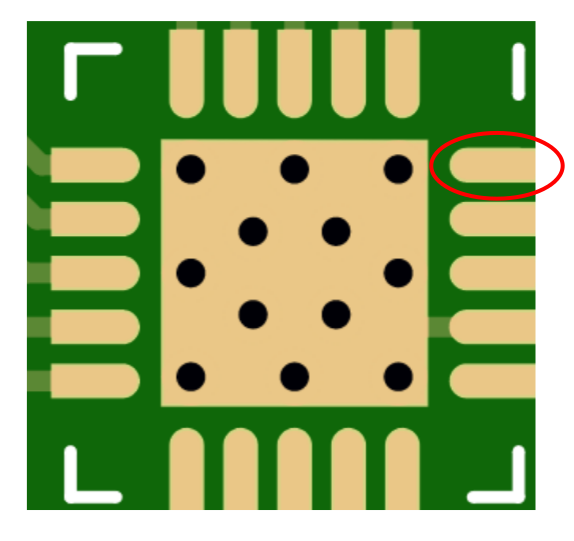
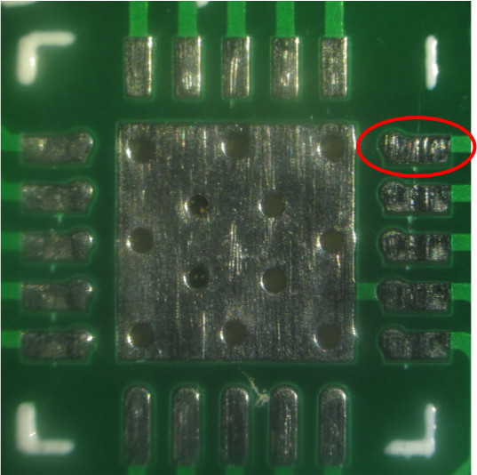
Unfortunately, this wasn’t the last instance of CAM software having difficulties with apterture macros. Ordering PCBs that used a QFN fooprint with D-shaped pads (Padstack SMD half obround) from JLCPCB turned up with some of these pads mangled.
That’s how the footprint is supposed to look:
And this is what I received:
The obvious next step then was to find out which CAM software JLCPCB uses. Fortunately Strange Parts stopped by the CAM department during his factory tour. We can clearly see, that they’re using CAM305 as well! Seems that’s the CAM tool of choice among far-east PCB factories. Downloading a demo copy of CAM350 and opening the Gerber files confirmed my suspicion that the issue is with CAM350 once more:
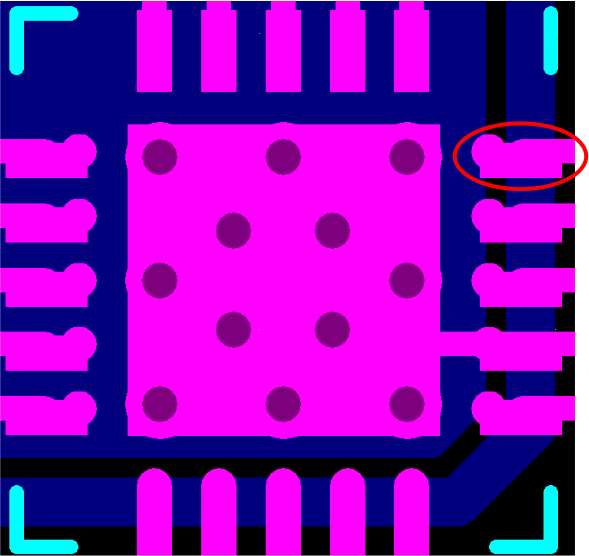
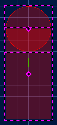
Looking at his a bit more closely reveals that the rectangular part of the padstack (see image below for reference) is always shifted downwards even if it should be shifted to the left. Guess what? The developers of CAM350 got the order of translation and rotation wrong in exactly the same way as the gerbv people and me! That’s at least three people independently misreading the gerber file format in the the same way.
Now we’re left with the task of working around broken CAM software
without introducing a check box “Fix aperture macros for (one
particular version of) CAM350, but break them for everyone else.”
Telling far-east PCB factories to update their CAM software is likely
not to have the desired result either.
The workaround that finally got implemented is exporting rectangles in padstacks that aren’t at the origin as a contour rather than a center line since these can be written in a way that doesn’t make assumptions on the CAM software correctly following that part of the gerber standard. This results in insignificantly larger gerber files and isn’t expected to have any other negative side effects as it’ll produce the same image as an actual rectangle, so this workaround is here to stay.