Progress Report September - December 2021 (What's new in Version 2.2)
Hierarchical schematics
TL;DR just tell me where to find it
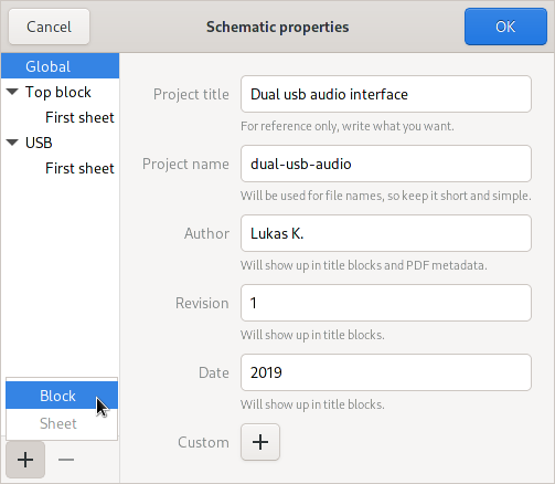
Open the schematic properties dialog either from the hamburger menu or by clicking on the three dots in the sheet list. There, click on the plus icon to add a new block.
How it came to be
Ever since the beginning of Horizon EDA, I’ve had in mind to eventually support hierarchical schematics. So when I defined the format for project files, I made provisions for hierarchical designs by supporting multiple netlist blocks. Each block would then be edited in its own instance of the schematic editor.
Over the course of time people came back asking about hierarchical schematics and I thought off-and about how to implement it.
After pondering how multiple instances of the schematic editor would interact with each other, I came to the conclusion that having multiple instances of the schematic editor would be confusing and complicate attaining a good user experience. On the other hand, I still wanted each block in the hierarchy to have its own netlist and schematic file. In the original design, the names of these files would have been stored in the project file. This however would have been impractical as the the project file is written by the project manager and not by the schematic editor. Storing them in the top-level netlist also seemed the wrong thing to do.
That’s why projects now have an additional file blocks.json storing
the filenames for netlists, schematics and and block symbols.
With question of where to store things out of the way it came to teach the schematic editor how to edit multiple blocks. For that, I went with the same approach I took for editing multiple sheets by globally selecting which block is currently being edited. Back when I made that decision for sheets, that approach felt a little hacky, but worked out well without any bad surprises, so I felt comfortable doing the same for blocks.
Similar to virtually any other schematic entry tool that supports hierarchy, blocks are connected through ports, with one significant difference though. Instead of ports being separate objects with their own name, ports are defined by setting the “is port” flag on a net. I’ve always found it confusing when port names could differ from the net they’re connected to.
To represent instantiated blocks on a sheet, each block is accompanied by a block symbol. To edit it, the schematic editor morphs into the block symbol editor. While this took more effort than creating a a dedicated block symbol editor, it yielded a much more consistent user experience.
With all of the infrastructure in place for editing blocks and block symbols, it became time to implement instantiating blocks to finally create hierarchy. This required a new way of storing component’s reference designators and do not populate flags since one component can now go by multiple reference designators, depending on how often the block it sits in got instantiated. To do so, the top block contains a map of all instantiated blocks in the whole design in which each item describes the mapping of component UUID to reference designator and do not populate flag.
A similar problem cropped up for sheet numbers. In a flat design, one could directly look at a sheet’s index to determine its page number. For hierarchical designs however, a sheet’s page number also depends on the page count of instantiated schematic blocks that go before it, requiring a complete view of the design. Since that complete view isn’t available in all places that require page numbers, they’re computed and stored in the top schematic.
Non-top blocks can either be edited within or outside of the hierarchy. In the former case, the editor fills in the reference designators from the top block’s instance map and takes care of saving any edits to reference designators and do not populate flags to the instance map rather than to the component itself. This creates the illusion of all instances of a block being kept in sync, where there’s just one schematic with different reference designators filled in.
Net classes and power nets are global to all blocks to keep things simple and consistent. It’s implemented by copying them from the top block to all non-top blocks.
The sheet list in the left sidebar that’s been virtually unchanged since forever got extended to a tree that shows the hierarchy:
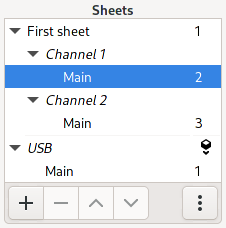
The section below the separator line shows all non-top blocks, even if they aren’t instantiated anywhere. Selecting the block (USB in the screenshot) itself switches to the symbol editor view.
A pathbar-like widget sitting above the schematic shows the current position in the hierarchy and makes useful tools more discoverable:

I copied the styling of the pathbar from GNOME’s Dconf Editor for its pretty look.
Apart from the schematic editor itself, other parts of the application such as annotation, BOM and PDF export also required enhancement to properly support hierarchical designs. For easy navigation in the exported PDF, the table of contents reflects the hierarchy and block symbols link to the corresponding sheet.
For use with the board editor, the hierarchical netlist is flattened by recursively expanding all instantiated blocks. This requires generating unique and predictable UUIDs for components and nets from instantiated blocks. For this purpose, version 5 UUIDs specified in RFC 4122 come in handy as they describe how to derive UUIDs from arbitrary data. To compute a version 5 UUID, one prepends the input data with the binary representation of a namespace UUID, calculates its SHA1 hash which then gets truncated to 128 bits and has a couple of bits replaced to indicate the UUID version. In our case, the arbitrary data consists of the instance path, i.e. the list of all instance UUIDs leading to a particular component or net, and the UUID of the component or net itself. That way, the board editor only required minimal changes related to cross-probing.
All in all, this added about 6000 lines of code. At the time of this writing, Horizon EDA itself is slighly more than 140.000 LOC1.
Align and distribute tool
Similar to the tools available in Inkscape, Horizon EDA can now align and distribute objects:
Hovering over the buttons shows a preview of what’s going to happen when clicking on it.
Where to find it: Select the items you want to move and search for align in the spacebar menu.
Part prefix override
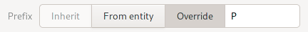
Some entities such as the ones for generic multi-pin connectors are supposed to be used for pin and receptacle headers. However, pin headers go by the “P” reference designator whereas receptacles use “J”.
To enable correct reference designators for these cases without having to duplicate the entity, parts can now override the reference designator prefix set by the entity:
Where to find it: Part editor
Shorted pads rule (PR #629)
Thanks to Erik for contributing this feature and this section.
When designing single layer PCB 0 Ohm bridges are strictly necessary. As such they are considered components by Horizon EDA and thus they have to be added in the Schematic of the board you want to design. However Horizon EDA doesn’t have a clue about the fact that the two pads of a 0 Ohm resistor can be considered shorted and shouldn’t result in an airwire making the preflight airwire check kind of annoying to deal with on a board with more than 50 such bridges.
To tackle this problem the easiest solutions would be to adjust the schematic such that both sides of a bridge are two separate nets. While working this would result in a hard to read schematic. Another solution would be to give the user the ability to place 0 Ohm resistors like vias on the fly while routing tracks. Whilst being quite a nice solution in terms of usability it comes with a whole string of issues when trying to implement. To name a few: Special handling to have it appear in the BOM, basically needing to reimplement the reference designator for silkscreen and component list, …
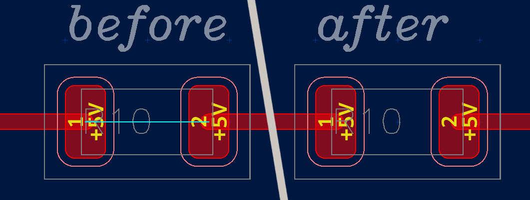
After a bit of thinking the best solution in terms of implementation effort and usability was to introduce the shorted pads rule which allows the user to specify a part or component to match and consider the pads shorted for airwire display. This allows the user to simply connect the 0 Ohm resistor with both pins to the net that should go through it at an arbitrary point in the schematic or even a different sheet.
Where to find it: “Shorted pads” in the board rules.
Exposed copper to silkscreen clearance (PR #633)
Thanks to Erik for contributing this feature and this section.
While designing a very cluttered board I noticed that there was no check to indicate a silkscreen being on an exposed copper pad. This was especially funny as there was already UI to enable such a check and configure the clearance to use. As there was quite enough code on how to use clipper this was an easy fix.
Dark theme
Gtk’s default (and only?) theme Adwaita includes a dark variant. On Linux desktop environments, there usually is an option to globally select the dark variant. On Windows though, Gtk doesn’t automatically pick up the global dark mode setting.
To allow users to experience Horizon EDA the way they like, there now is a dark mode switch in the editor preferences.
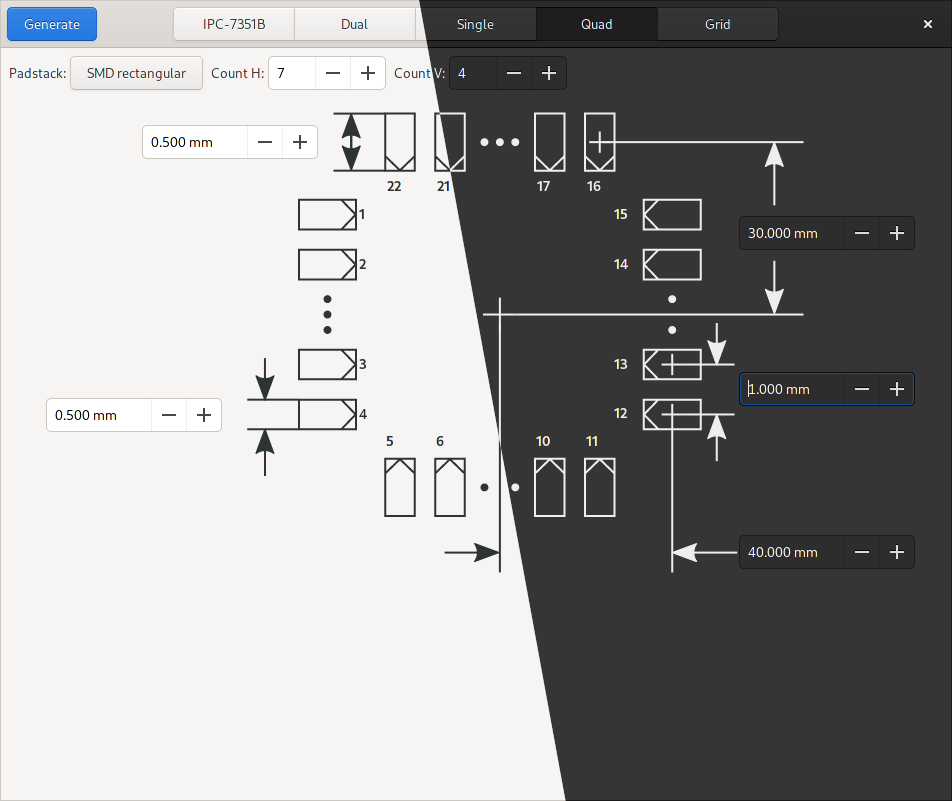
Apart from that, the footprint generator’s graphics are automatically recolored to match the current theme:
Rendering performance improvements
Robin’s pull request
and the subsequent discussion on IRC motivated me to have another look
for low-hanging fruits to make rendering faster. Profiling with perf
and hotspot yielded some opportunities for easy speed improvement,
mostly focused on avoiding reallocations:
Use a std::vector rather than a
std::list to store the
transformation stack since pushing and popping from a vector won’t
incur memory reallocations once the vector has grown to a sufficient
size.
The placement class contains fast paths for 90 degree rotations as
these can be done without sine/cosine computation. A missing else
in an else
if caused it to take the slow path for the trivial 0
degree case, oops. I only spotted this since the sine computation
showed up bigger in the flame graph than expected.
A missing & near
auto caused a vector to get copied every time a
single character was rendered.
Each line of text is rendered into an intermediate buffer before being drawn onto the canvas so that its extents can be determined beforehand as it’s necessary for right-aligned text. Due to laziness, that buffer got reallocated on each line. Moving that buffer to the Canvas, where it’s only allocated once got rid of some reallocations.
Undo/redo popups
Using undo and redo sometimes left me wondering about what I just undid. The first step into fixing this was storing the name of the current tool in the undo history. Once that was done, adding an overlay that appears on undo/redo was fairly straightforward. The overlay briefly disappears if it is still visible during the subsequent undo/redo action to indicate that a new action was triggered.
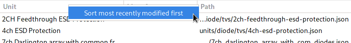
Sorting pool items by modification time
When creating or placing a new part, one often needs to use other items that just got created or modified. To simplify this, the pool browsers in the create part dialog are now sorted by modification time. Since there’s no visible modification time column, sorting my modification time can be selected by right-clicking the column headers:
Windows specifics
For for stock information and GitHub integration, Horizon EDA talks to the outside world over HTTPS using curl and libgit2. Both of these use OpenSSL for TLS by default. On Windows, it requires shipping a certificate bundle of all root certificates. This is far from optimal for two reasons:
-
Users need to trust Horizon EDA to not ship a malicious root CA certificate that could be used to intercept the application’s communication with the internet.
-
Users sitting behind a corporate MITM proxy that terminates TLS and re-signs it with a certificate that’s trusted by Windows aren’t able to use the aforementioned features since the cert isn’t trusted by the certificate bundle that ships with Horizon EDA.
While the first issue is mostly of theoretical importance, I know of at least one user being affected by the second one.
Rather than trying to convince OpenSSL to use the Windows certificate
store, I found out that both curl and libgit2 can use Windows’ crypto
infrastructure instead of OpenSSL, if compiled with the right options.
For curl this was as easy as as substituting the MSYS2 package
mingw-w64-clang-x86_64-curl for mingw-w64-clang-x86_64-curl-winssl.
For libgit2 however, such package didn’t exist so I had to make
it. With these
changes in place, I could finally
remove
the certificate bundle and the Windows-specific code to locate it.
Security enhancements
SQL injections
Talking about SQL injections with a friend made me realize that parts of Horizon EDA are vulnerable to them. In almost all places, where user-supplied data is used in SQL queries, this is done using parameters, making SQL injections impossible. For the definition an usage of parametric tables however, user-supplied strings are used in SQL queries by means of string concatenation since table and column names can’t be supplied as parameters, opening the door for SQL injections. This means that a maliciously-crafted pool or project could run arbitrary SQL statements to exploit a vulnerability in SQLite. To prevent this, user-supplied table and column names are validated to only contain word characters, that is lower and upper case letters, numbers and underscores.
Inter-process communication
Horizon EDA uses ZeroMQ over local TCP sockets for inter-process communication
between the main application horizon-eda and editor horizon-imp.
Port numbers are assigned randomly on startup and passed to editor
processes through environment variables. Due to the nature of TCP
sockets, every other application running on the same computer could
connect to and interact with Horizon EDA through these sockets after
guessing the port number. This isn’t a problem for applications running
as the same user as Horizon EDA as these wouldn’t gain any additional
privileges by interacting with Horizon EDA.
Applications running as a different user though could gain access to a running instance of Horizon EDA.
To protect against this, the pool/project manager creates a cookie in
the form of a UUID on startup. It is provided to the editor processes through an
environment variable. Requests on the IPC socket are only accepted if
they contain the correct cookie. This doesn’t change the situation for
processes running as the same user as Horizon EDA as these can just get
the cookie by inspecting /proc/<pid>/environ of an editor process.
Processes running under a different user though don’t have access to
the cookie and are thus prevented from making valid requests. The same
applies for web applications, though I’m not sure how far one will get
by using HTTP or web sockets talking to ZeroMQ.
H is for hierarchy
Now that hierarchical schematics have been sitting on the master branch for a few months, it’s about time for version 2.2 “Halo”. See the changelog for a list of all enhancements and bugfixes included in this release.
-
find src \( -name \*.cpp -o -name \*.hpp -o -name \*.c -o -name \*.h \) -print0 | xargs -0 wc -l | sort -nand manually subtract fonts ↩