Progress Report January 2021
3D preview enhancements
To improve the appearance of models in the 3D preview, these are now rendered using interpolated normals. Additionally, shading now takes gamma correction into account, resulting in a more realistic appearance:
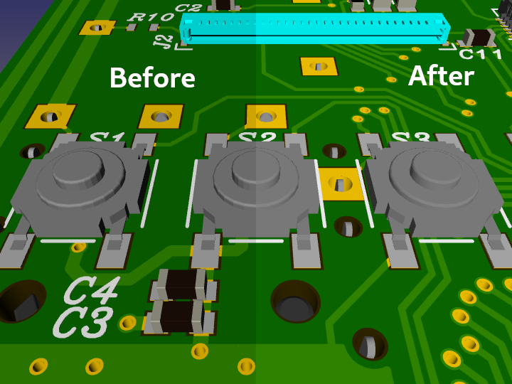
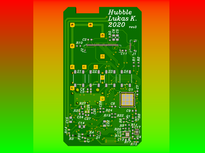
The background gradient is also rendered gamma-correctly. The outer portion of the image shows the incorrect gradient, as it was rendered before. The center portion is rendered correctly with the blending being done in linear color space. Mixing red and green actually produces yellow rather than brown.
Canvas rotation
When assembling or debugging boards, I often wished I could see the board on screen whatever way I was holding it. While the “bottom view” option took care of flipping the board to the other side, I still had to rotate the board in my mind. Since I don’t like doing things my computer could to for me and I know how to make computers do things, Horizon EDA now supports rotating the board (and package) view by arbitrary angles:
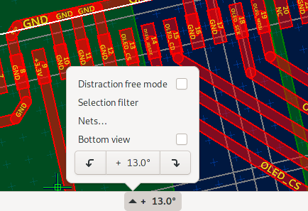
The hard part implementing this was getting the box selection and grid to work correctly regardless of the current angle.
Improved thermals generation
For more than three years planes supported using thermal spokes for connecting pads as way to improve solderability. However, certain circumstances could lead to the generated spokes being closer to other copper objects than specified in the rules. This was due to the thermal spokes being generated after the polygon was expanded to account for the minium width rule. To fix this, thermal cutouts and spokes are now computed before the minium width constraint is applied. Furthermore, the plane with added thermal spokes is clipped to the original plane without spokes to protect against spokes poking out of the intended plane outline.
Measure tool
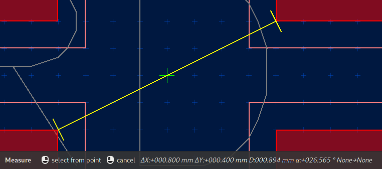
I’ve found myself using dimensions for measuring distances and deleting them right after I got the reading. As this is quite cumbersome, there’s now a tool explicitly for measuring distances:
Symbol expand preview
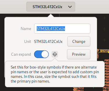
To accommodate pin names of varying length, symbols can be set to be expandable in the schematic. That way a symbol’s width can be adjusted in the schematic to avoid overlapping text. Even though this feature existed for more than 2 years it wasn’t really obvious how to use it as various pull requests from users indicated. To be fair, there wasn’t much explanation given what the “can expand” switch does and when to set it.
There now is a help button next to the switch that explains its purpose:
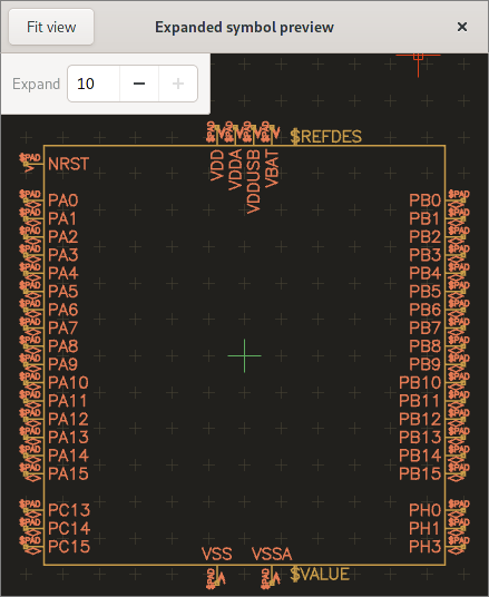
Additionally, the preview button opens a window that allows the user to see what the expanded symbol will look like:
Pool download progress reporting
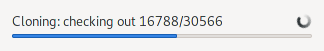
Testing the pool download on a computer running Windows showed that progress reporting was inadequate as checking out the cloned repo and copying took quite long with no visual feedback other than a spinning circle. To give the user more to look at, the pool manager now shows a progress bar for download, checkout and copy operations:
Version 1.4
As per the release schedule, version 1.4.0 got released on 2021-01-29. See the changelog and this and the prior progress reports for features that made it into the release.
Apart from the usual set of new feature this release includes two important bugfixes for windows users:
- No more laggy rendering on Intel GPUs
- 3D preview doesn’t crash randomly with “gl error 1285”
What’s next
A comment on the future of the horizon-pool repo issue got me thinking what could be done do make it easier to mix-and-match pools. Even though I haven’t quite decided yet on how to evolve the horizon-pool repo, it’s definitely worth replacing the pool cache by a pool to make it easier to use multiple pools in a project. That’ll also solve some consistency issues such as the results in the part browser not reflecting the state of the pool cache.
Apart from that I did some experiments for selecting packages in the 3D preview. Selection by itself is working, but there’s still some integration and cleanup work left to be done.
When creating packages for parts with a complex outline such as connectors I often use FreeCAD to create a 2D projection of the part and import it into the package editor as a reference for drawing the outlines. To make this possible in Horizon EDA, I implemented a proof of concept based on Open CASCADE’s hidden line removal algorithm that dumps the lines to text file to be visualized with gnuplot. When done, the package editor will be able to load these lines as an overlay that can be used to draw the package’s outlines.