Progress Report February 2021
Show check result in remote/git tab
The introduction of the poolbot made reviewing pull requests to the default pool significantly easier as it provides an overview of all items in the PR and lists all of their check results. Still, it’s up to the submitter to make sure that all checks have passed before creating the PR. To make their lives easier, Juergen suggested adding the check results to the pool manager itself. Having also thought about this very feature, I went ahead and implemented it. For completeness, the git tab in the pool manager shows the check results as well.
Parametric data in schematic
To clearly communicate design intent, it’s good practice to include relevant attributes such as capacitor’s rated DC voltage or a resistor’s tolerance in the schematic. In Horizon EDA much of that information is already available in part’s parametric data.
With custom values on symbols, there now is an easy way to add parametric data to the schematic:

Apart from the Group&tag display, this feature is the main reason to make sure that multi-line value text on symbols doesn’t overlap with the symbol body.
KiCad package importer window
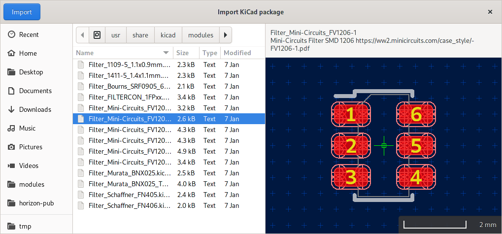
Ever since the package editor supported importing KiCad packages, some users had trouble finding it as it was hidden in the package editor’s hamburger menu. To make it easier to find, it got it’s own button in the pool manager’s package tab similar to the KiCad symbol import wizard.
The import window also makes selecting the right package easier as it provides an instant preview of what’s to be imported:
Cursor in tools
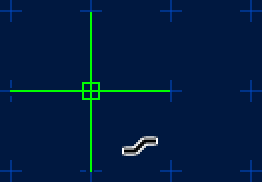
A friend of mine using Horizon EDA for his first board layout told me that he had difficulties telling if some tools such as draw line or route track were active as they provide very little visual feedback other than the bar at the bottom of the canvas when not having started a line/track. He suggested changing the cursor to reflect the current tool as it’s standard among many graphics-related applications.
I settled on replacing the system’s cursor in that case as it isn’t all that useful after all in tools since they only operate on the grid-based canvas cursor. To ensure optimum visibility regardless of background color, the tool’s icon is rendered with a white border. This is accomplished by creating a mask from the icon outline and rendering it offset by ±1px in both axis. The idea for this came from Gtk’s code for drawing shadows on icons based on CSS properties.
Here’s how it looks like on a ×2 scale:
Part wizard package preview
In issue #566 MarSik suggested showing the the package in the part wizard. After a bit of clarification, this made sense to me, so the part wizard now looks like so:
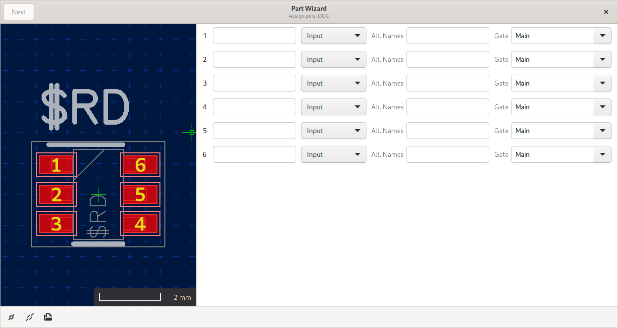
Selecting a pad in the list will highlight it in the package preview.
3D preview
Picking
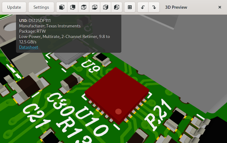
I though it’d be useful if one could click on a package in the 3D preview and find more about it, such as reference designator and part number. For this, we first need to figure out which package is at a given pixel position. In the context of 3D rendering, this is often referred to as picking.
There are two ways this can be done: One involves casting a ray
from the cursor position and figuring out which of the 3D models the
ray intersects with. This has the downside that all of the model
placement and transformation has to be redone in software and has a chance of
not matching what’s on screen. Wouldn’t it be nice if we could reuse
the transformations the GPU is doing anyhow? Turns out we can by
attaching another colour buffer to the framebuffer and rendering each
package with a distinct
colour.
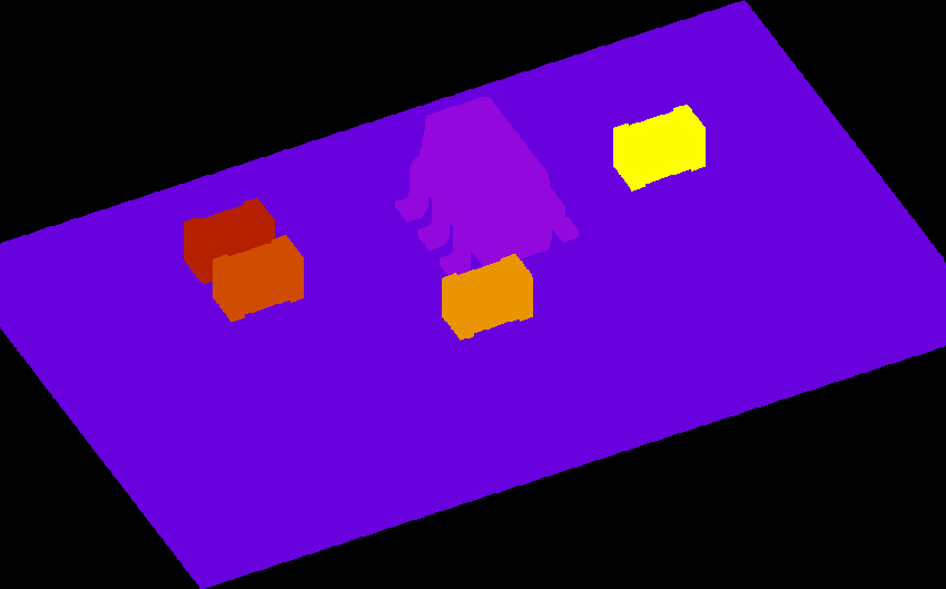
In our case, the aforementioned colour isn’t really one with R, G and B
components, but rather an unsigned 16 bit integer. As models are
rendered using instancing, we get this distinct colour almost for free
from gl_InstanceID. All that’s needed is adding an offset for each
model to tell them apart. For illustration, this is what the pick buffer looks like for a
simple board:
Once the GPU has rendered the board, the pick buffer is downsampled (can’t
read from multisample buffers) and read back using glReadPixels. Since
glReadPixels can be slow, the pick buffer is only read if the user
actually clicks on something, so zooming and panning stays smooth. With
the pick buffer in main memory, all that’s left to do is get the value
at the coordinate and look up which package it belongs to.
Details on the currently selected package are displayed in a head-up display style similar to the board editor:
Model alignment
When adding support for importing STEP models, I was initially hesitant to add support for translating (and rotating) the model as I feared that users will eyeball these rather than taking measurements on the model itself, resulting in inaccurate model placement.
The recommended, probably not documented, way to place the model instead is to use a proper 3D CAD tool such as FreeCAD and place the model by aligning its features to the origin. Apart from introducing another tool into the workflow, modifying vendor-provided models means that other users downloading the model now have to replicate the placement on their end.
By now, it should be clear that we want to be able to align 3D models in Horizon EDA itself without the use of external software. The first step in this process is picking points from the 3D model. To do so, we need to extract corners from the model and make them selectable on screen. Extracting the corners got implemented as part of the STEP importer as it’s already traversing the model’s geometry. Once extracted, the points are rendered with a slight depth offset added in the fragment shader to make sure that they appear on top of the model. To make the points selectable by clicking, the picking infrastructure described above then got extended to also support picking points.
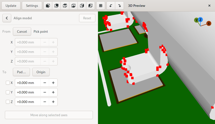
Aligning the model is a two-step process. First, the user enters the from coordinates, either by picking a single point or two points to get their average value for centering models. Second, they enter and select where the previously entered point should be at after moving.
Axes arrows
Using the model alignment feature for while, it quickly became imminent that there’s the need for the user to see which axis is pointing in which direction. In fact, most if not all CAD or modelling applications have some sort of XYZ arrows for this purpose. The ones from blender struck me as particularly well done and nice to look at:
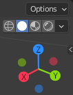
About 100 lines of code later, the 3D preview has something that looks roughly the same.

Since the arrows look roughly like lollipops, the widget is called
AxesLollipop.
Projection
As hinted in the last progress report, I did some experiments with Open CASCADE’s hidden line removal algorithm for projecting 3D models. With the hard work of dealing wih Open CASCADE done, the the only missing piece was to hook up the code to the 3D preview and the package editor.
With this feature in place, clicking on the Project button, takes us from this
to that.
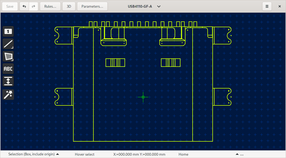
To aid drawing the outline, the corners and arc centers of the projection are targets that tools can snap to.
STEP export speed improvements
Exporting moderately large board as a STEP model, I noticed that the exporter was taking surprisingly long to create the board body. It’s constructed by extruding the board outline to a prism and then subtracting cutouts and holes. Holes for example were represented as cylinders. On top of that, it took one call to Open CASCADE to process every negative feature. By this description, it should be obvious that doing the subtraction 3D isn’t strictly necessary as the final shape also is a prism with holes that could as well be created by extruding a face with holes.
Having gained a bit more understanding of Open CASCADE from the other recent 3D model related features, I implemented exactly this. In that process, I also discovered that Open CASCADE supports subtracting an arbitrary number of shapes in one go, potentially making use of multi threading. These optimisations, most likely the second one, decreased the export time from over 100 seconds to about 3 seconds. Even tough such a dramatic improvement is nice, it’s also kind of embarrassing since it was that slow to begin with.
Treeview/paned state store
After all of the shiny new 3D features, now over to something much more mundane. I’ve found it difficult to determine default layouts for list views and paned widgets that work in all cases, so after opening the pool manager or similar views, I’ve often found myself readjusting column widths and splitter positions to my liking. To make Horizon EDA look less stupid, these are now stored persistently in an SQLite database similar to the window positions.