Progress Report May - October 2022 (What's new in Version 2.4)
Curved tracks
KiCad adding support for curved tracks in version 6.0 motivated me to update Horizon EDA’s copy of their router to also support curved tracks and benefit from other developments that happened since the last time I updated it. As always, updating the router is a somewhat daunting task since it’s not a library with with a stable API, so its interface can change in arbitrary ways between releases and there’s no documentation apart from the code itself.
One particular annoying aspect of integrating the version 6 router was that it now
also uses the excellent clipper library for polygon operations, but
with different compile-time options. To prevent the two copies of
clipper from clashing with each other, I had to put the one for the router in
a different namespace and prefix all defines.
Adding curved tracks in itself wasn’t all that difficult and resulted in a diff of less than 500 lines. It also greatly benefited of past enhancements for rendering and selecting arcs.
Cursed footprints
Apparently, there are technical reasons for some parts to require footprints as complicated as this one:

The above drawing is from the datasheet of the SiC437 buck converter.
Using this part in a project was good opportunity so see how hard it is to draw such a footprint in Horizon EDA and what could be done to make it easier. See the newly-added section in the docs for tips on dealing with such footprints.
As it so happens, this exact part was featured on the Cursed Footprint Twitter account shortly after I used it.
Schematic keeps labels on unconnected nets
A common way of creating connectivity in schematics is copy/pasting net labels from one place to the other. In that process, the net label may not be connected to any component. In Horizon EDA, a net label not connected to anything loses its net as the net assignments are derived from the components the label is connected to.
To fix this, net labels now remember the last net they were connected to so this way of creating connectivity also works in Horizon EDA’s schematic editor.
Vertical tool bar
While the introduction of the reflowing tool bar prevented the bar from overflowing the resulting layout still was suboptimal for tools with many actions such as the router:

There now is an option in the editor preferences to show the tool tip below the keyboard shortcuts:

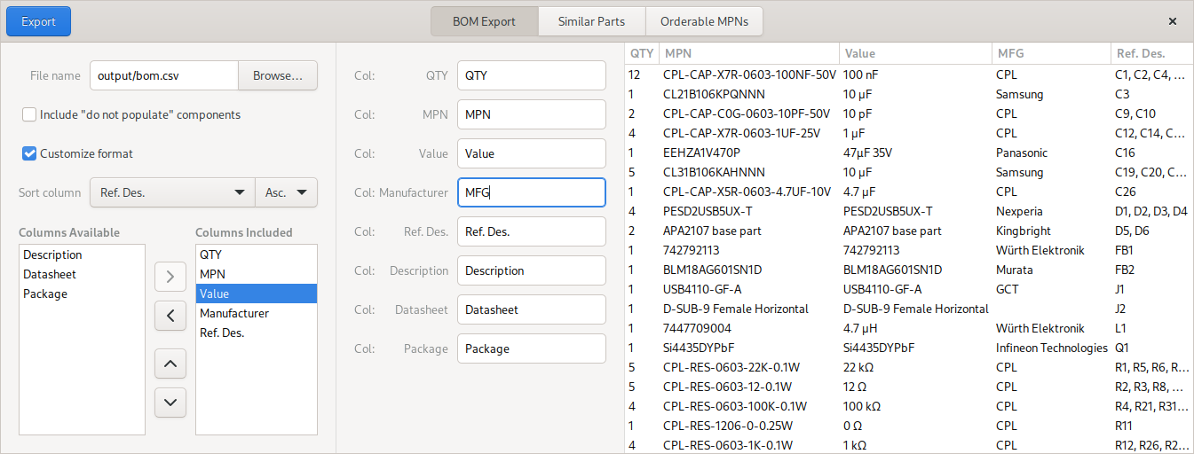
BOM format customisation
Similar to the Pick&Place export, the BOM export now supports customising the column names to suit the requirements of assembly houses.
Prompting for filenames for new items
When creating a new symbol, padstack or package, the pool manager first
prompted the user for a filename before opening the empty editor rather
than directly opening the editor and allowing the user to decide on the
filename later on. This implementation was a remnant of the very early
days of the project back when the pool manager didn’t exist and the
editors had to be launched from the command line with an existing file.
To still keep the overall architecture similar, but allow the user to pick the filename after opening the editor, the pool manager now creates a temporary file and opens the editor with it. The editor then deletes the temporary file and asks the user for the filename when saving the new item for the first time.
Part browser for assigning parts
Motivated by Issue #682, the schematic editor now uses the part browser window for assigning new parts to components. While there has been the “Assign Part” button in the part browser for a long time, it wasn’t very discoverable and didn’t provide any meaningful feedback when trying to assign a part to a component of the wrong entity.
The new “Assign Part” action temporarily reconfigures the part browser to only show parts of the matching entity and double-clicking a part will assign it to the selected components rather than placing it.
Datasheet links in PDF export
Clicking on a symbol in a schematic PDF now takes one directly to the datasheet for the part.
Design reuse
Inspired by the EDeA project, I spent some time thinking about how to simplify design reuse and sharing in Horizon EDA. After experimenting with block-level design reuse by importing an entire project as hierarchical block, I deemed it’s easier to implement and of use to more people to improve design reuse by copy and paste.
Copying pool items
While copy/pasting schematics from one project to another was possible for a very long time, all parts, symbols, etc. used in the copied schematic had to be present in the destination project’s pool. If they weren’t the paste tool would crash.
To prevent this, the paste data transferred between source and destination schematic now includes the required pool items and the paste tool checks if all of them are available in the project pool. If that’s not the case, the paste tool copies all required items to the project pool and triggers a pool update. Once the pool update is done, the paste tool resumes its normal operation.
Apart from pasting subcircuits such as DC/DC converters from other schematics, this new capability can also be used to easily steal parts from other people’s projects.
Copying layout
The above improvement covers copying the schematic from one project to another, but we’re still without a way to copy the layout, so let’s fix that as well. The existing copy placement and copy tracks tools area a good starting point for this as they do almost exactly what we need. Their only shortcoming is that they don’t work across projects as they don’t use the system clipboard.
Starting with the copy tracks tool, it occurred to me that it’s essentially the same as the regular paste tool with the only difference being that it has to calculate the new placement with respect to a package rather than allowing the user to move things around. So I extended the existing paste tool to cover this use case as well and added some other required bits an pieces such as copying plane assignments and attaching tracks to packages.
For the new paste placement tool, the existing copy placement tool provided a good starting point and only had to be modified to use the package placements from the clipboard instead of another group on the board.
With these changes, we now have unified way of copying layouts that works for groups in the same level of hierarchy, for hierarchical blocks and across projects. See the docs for a detailed guide on how to use these tools.
Plane fragments are saved into a separate file
Stephie brought up that she always clears all planes before committing a board so that the repository and diffs are not cluttered with the calculated plane fragments and suggested saving them to a separate file. That way, one can choose whether to include the calculated planes into the repository or not. Since that suggestion made sense to me and was of low additional complexity, I implemented it.
For a boards with complex planes, especially with thermals enabled, this can significantly reduce the size of the repository as the calculated fragments can be about 10× the file size than the rest of the board.
Version 2.4
With all of these improvements and new features, the time is right for
the next release, version 2.4
“Jupiter”.
See the
changelog for a list of
all enhancements and bugfixes included in this release.